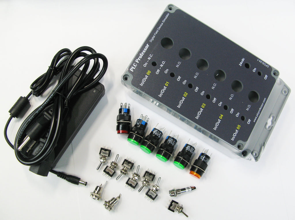
39 - Digital Field Device Simulator Enclosure (Machined and Printed) with all Major Components & with Instructions
Allow 30 days for high quantities...
This product is a fully machined and printed enclosure ready to receive the provided components to build a digital field device simulator. This system simulates six digital inputs and six digital outputs. The six digital input simulations allow four states: maintained off, maintained on, momentary on and momentary off.
Included with the enclosure is a complete set of instructions for mounting the components and wiring the system.
These can be ordered fully assembled and tested by quote only. Contact us with the quantity and we will quote them fully assembled and tested.
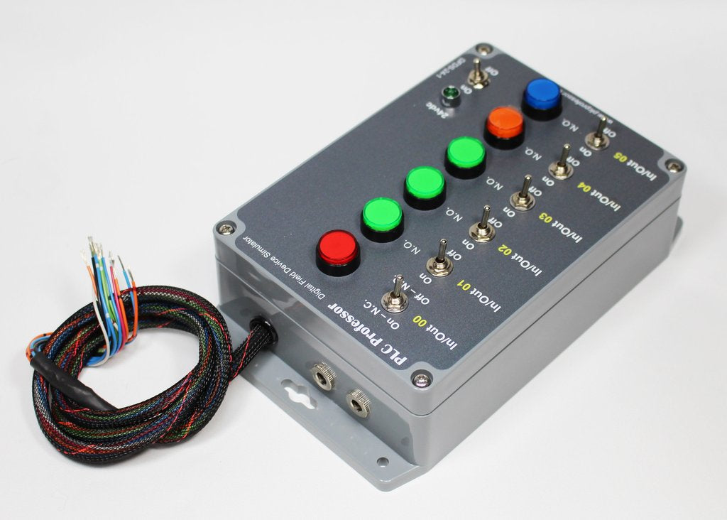
This design is for a universal I/O simulator with six multipurpose input simulators and six highly visible output simulators:
This field device simulator can be integrated with any controller, any size and any brand.
1. Six multipurpose input field device simulators:
Multi-state simulator; using a selector switch or a pushbutton alone can be awkward to operate when exercising your logic in the controller.
The electrical interface (field wiring) to the six input field device simulation is one common conductor to all six pairs of switches and one dedicated conductor per pair for landing on the I/O modules terminal block. They are not polarity sensitive, they are all dry contacts.
Maintained ON or Maintained Off - There are instances that you would like to change the state of a simulated input field device and leave it in that state indefinitely.
Normally Open or Normally Closed - There are other situations where a single hand motion to change the state momentarily reduces distraction from concentrating on the code and not the simulation of field devices. This is where a pushbutton is the best solution.
In most cases... A normally open pushbutton will suffice for the quick momentary change of state and for that reason all six of our input field device simulators have an adjacent pushbutton that functions as normally open when the toggle switch is in the maintained off position.
In00 - In05 - four state simulation:
Maintained Off or Normally Open
Maintained On or Normally Closed
2. Six highly visible illuminated indicators as output field device simulators:
The electrical interface (field wiring) to the six output field device simulation is one common conductor to all six 24vdc LED illuminated pushbuttons connected to the negative (ovdc - common) terminal of the indicators and one dedicated conductor per indicator for landing on the I/O modules terminal block. They are polarity sensitive, negative common and positive (24vdc) from each output terminal to each indicator. Integration with relay output modules is the simplest. Make sure that your output module is compatible with this circuit type.
Larger and multicolor indicators allow quicker determination of the state of the outputs controlled by your controller.
3. The enclosure has dual 24vdc power connectors connected in parallel to allow daisy chaining to additional field device simulations.
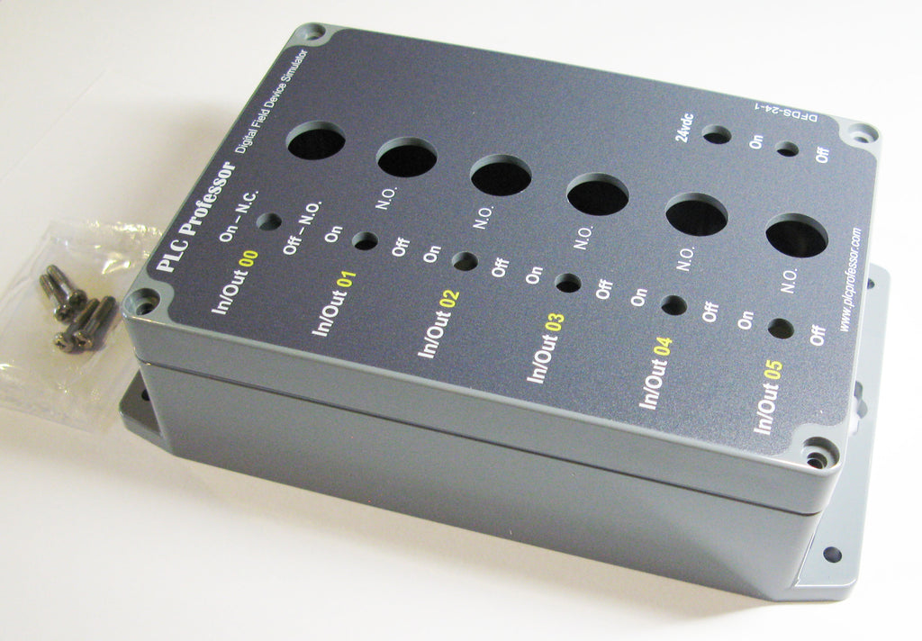
4. The enclosure is professionally machined and digitally printed.
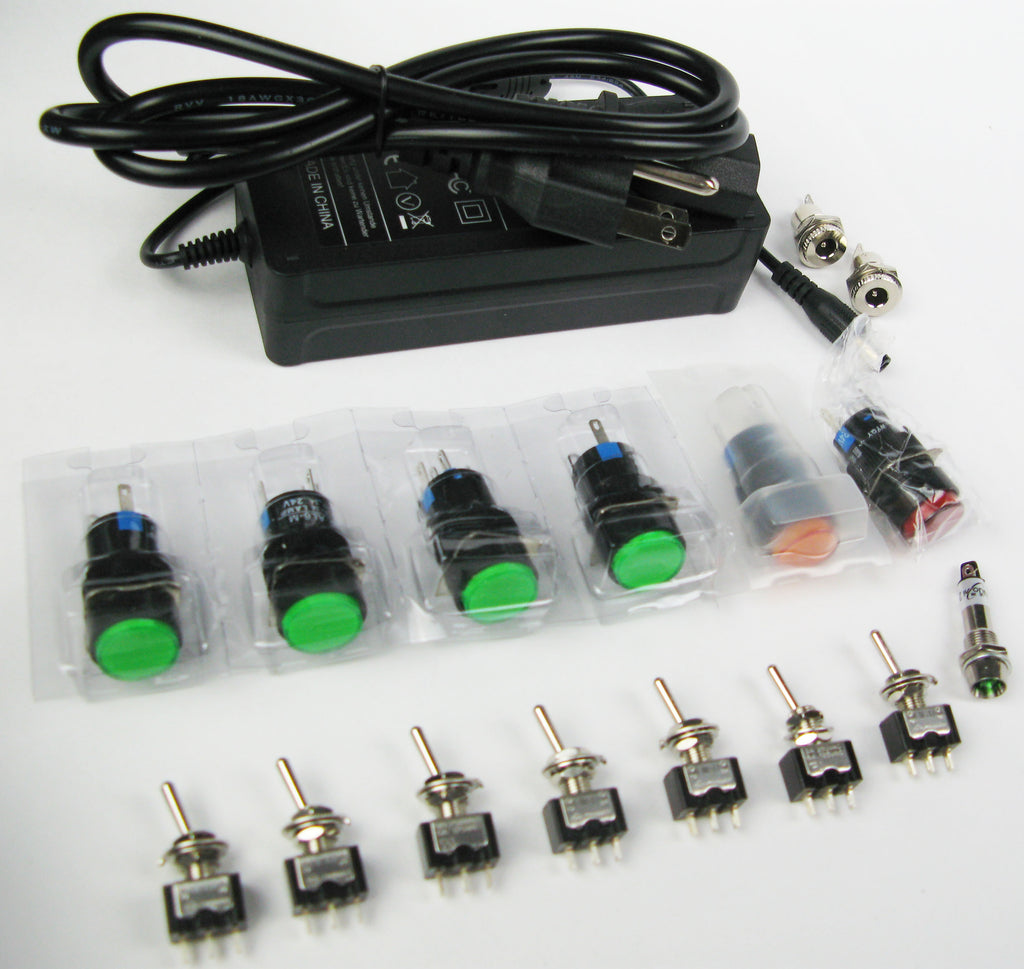
5. All of the major components are supplied with this kit. We do not supply solder, wire or tools but the instructions include information regarding where and what to purchase.
6. Three of the openings are bored to the smallest available components, 2 bulkhead connectors and the pilot light. You may have to increase the opening to accept those parts...be very careful not to oversize the openings. I suggest that you purchase a uni-bit as shown in the instructions and increase the opening one size at a time, checking the fit of the pilot light after each increase.