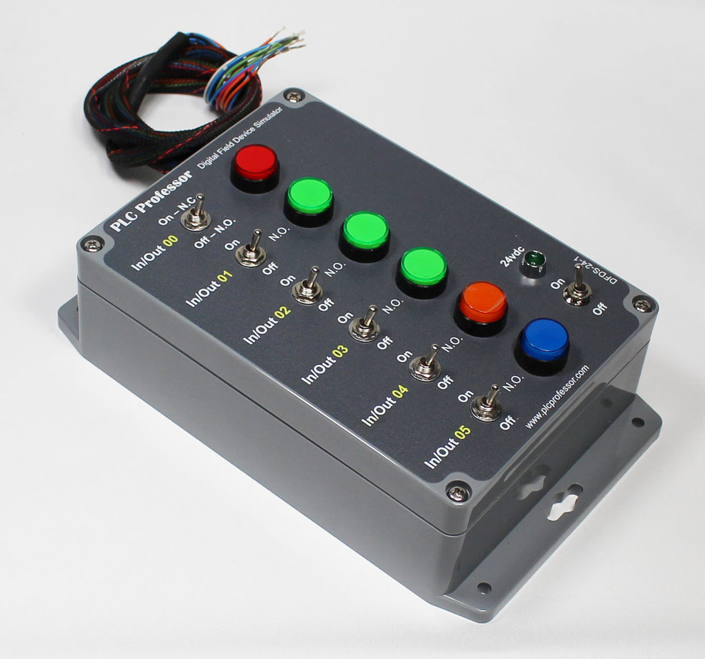
28 - Universal Digital Field Device Simulator - Use with PLC2/3/5, SLC500 - Micrologix1000, 1100, 1200, 1400, 1500 - ControlLogix or CompactLogix or any PLC with DC I/O
Please allow 7 to 15 business days for shipment of this product.
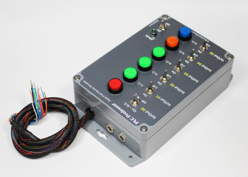
The simulators ship with 24" fly-outs (wires to connect to your controller).
A universal I/O simulator with six multipurpose input simulators and six highly visible output simulators:
This field device simulator can be integrated with any controller, any size and any brand.
1. Six multipurpose input field device simulators:
Multi-state simulator; using a selector switch or a pushbutton alone can be awkward to operate when exercising your logic in the controller.
The electrical interface (field wiring) to the six input field device simulation is one common conductor to all six pairs of switches and one dedicated conductor per pair for landing on the I/O modules terminal block. They are not polarity sensitive, they are all dry contacts.
Maintained ON or Maintained Off - There are instances that you would like to change the state of a simulated input field device and leave it in that state indefinitely.
Normally Open or Normally Closed - There are other situations where a single hand motion to change the state momentarily reduces distraction from concentrating on the code and not the simulation of field devices. This is where a pushbutton is the best solution.
In most cases... A normally open pushbutton will suffice for the quick momentary change of state and for that reason all six of our input field device simulators have an adjacent pushbutton that functions as normally open when the toggle switch is in the maintained off position.
In00 - In05 - four state simulation:
Maintained Off or Normally Open
Maintained On or Normally Closed
2. Six highly visible illuminated indicators as output field device simulators:
The electrical interface (field wiring) to the six output field device simulation is one common conductor to all six 24vdc LED illuminated pushbuttons connected to the negative (ovdc - common) terminal of the indicators and one dedicated conductor per indicator for landing on the I/O modules terminal block. They are polarity sensitive, negative common and positive (24vdc) from each output terminal to each indicator. Integration with relay output modules is the simplest. Make sure that your output module is compatible with this circuit type.
Larger and multicolor indicators allow quicker determination of the state of the outputs controlled by your controller
3. The enclosure has dual 24vdc power connectors connected in parallel to allow daisy chaining to additional field device simulations.
We include a 24vdc power adapter with this field device simulator. The power adapter has sufficient capacity to power at least two of our field device simulators.
We have not posted a photo of the power adapter because the physical form may vary, but not the capacity.
4. The enclosure is professionally machined and digitally printed.
5. Flyout leads are a minimum of 12 inches. Longer leads available for quote.